 salem salem
Member


Messages : 102
Inscrit(e) le: 09/01/2008
|
 Posté le 09/11/2013 08:46 Posté le 09/11/2013 08:46
 1383986761.png (64 Ko) 1383986761.png (64 Ko) | | | Résolu : mcp23s17 |
essalam
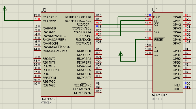
je suis bloquer pour fonctionnement d'un mcp23s17
je doit le faire avec ccs compiler j'ai deja essayer le driver fourni avec ccs compiler mais sur isis je voit les commande avec le SPI debugger mais rien ce change que ce soit sur les sortie de MCP ou bien les register de MCP
merci beaucoup si vous aves un aide
ce ci le driver de MCP:
///////////////////////////////////////////////////////////////////////////
//// ////
//// 23S17.c ////
//// ////
//// Library for a MicroChip MCP23S17 SPI Port Expansion Chip ////
//// ////
//// The MCP23S17 device provides 16-bit, general purpose parallel I/O ////
//// expansion for SPI applications. The 16-bit I/O port functionally ////
//// consists of two 8-bit ports (PORTA and PORTB). There are two ////
//// interrupt pins, INTA and INTB, that can be associated with their ////
//// respective ports, or can be logically OR’ed together so that both ////
//// pins will activate if either port causes an interrupt. The ////
//// hardware address pins are used to determine the device address. //// ////
//// ////
//// A #use spi must be provided by the main program. ////
//// ////
//// ------------------------------------------------------------- ////
//// PIN LAYOUT ////
//// ------------------------------------------------------------- ////
//// ////
//// ------------------------------------------- ////
//// | 1 : GPB0 | 28: GPA7 | ////
//// | | | ////
//// | 2 : GPB1 | 27: GPA6 | ////
//// | | | ////
//// | 3 : GPB2 | 26: GPA5 | ////
//// | | | ////
//// | 4 : GPB3 | 25: GPA4 | ////
//// | | | ////
//// | 5 : GPB4 | 24: GPA3 | ////
//// | | | ////
//// | 6 : GPB5 | 23: GPA2 | ////
//// | | | ////
//// | 7 : GPB6 | 22: GPA1 | ////
//// | | | ////
//// | 8 : GPB7 | 21: GPA0 | ////
//// | | | ////
//// | 9 : Vdd | 20: INTA | ////
//// | | | ////
//// | 10: Vss | 19: INTB | ////
//// | __ | _____ | ////
//// | 11: CS | 18: RESET | ////
//// | | | ////
//// | 12: SCK | 17: A2 | ////
//// | | | ////
//// | 13: SI | 16: A1 | ////
//// | | | ////
//// | 14: SO | 15: A0 | ////
//// ------------------------------------------- ////
//// ////
//// ------------------------------------------------------------- ////
//// FUNCTIONS ////
//// ------------------------------------------------------------- ////
//// ////
//// void IO_INIT() ////
//// Initializes the 23S17 chips on the SPI bus ////
//// ////
//// void IO_WRITE_REGISTER(int8 address, int8 reg, int8 data) ////
//// Writes the value to the specified register and device ////
//// ////
//// int8 IO_READ_REGISTER(int8 address, int8 reg); ////
//// Reads the value of the specified register and device ////
//// ////
//// void IO_OUTPUT_A(int8 address, int8 data); ////
//// Outputs the value to PORTA on the specified device. Doesn't ////
//// change the direction of the port. ////
//// ////
//// void IO_OUTPUT_B(int8 address, int8 data); ////
//// Outputs the value to PORTB on the specified device. Doesn't ////
//// change the direction of the port. ////
//// ////
//// int8 IO_INPUT_A(int8 address) ////
//// Returns the value of PORTA on the specified device. Doesn't ////
//// change the direction of the port. ////
//// ////
//// int8 IO_INPUT_B(int8 address) ////
//// Returns the value of PORTB on the specified device. Doesn't ////
//// change the direction of the port. ////
//// ////
//// void IO_OUTPUT_BIT(int8 address, int8 pin, int1 state) ////
//// Outputs the value to specified pin and device. Doesn't change ////
//// the direction of the pin. ////
//// ////
//// void IO_OUTPUT_HIGH(int8 address, int8 pin) ////
//// Sets the output high on the specified pin and device. Doesn't ////
//// change the direction of the pin. ////
//// ////
//// void IO_OUTPUT_LOW(int8 address, int8 pin) ////
//// Sets the output low on the specified pin and device. Doesn't ////
//// change the direction of the pin. ////
//// ////
//// void IO_OUTPUT_FLOAT(int8 address, int8 pin) ////
//// Sets the pin to an input on the specified device. ////
//// ////
//// void IO_OUTPUT_TOGGLE(int8 address, int8 pin) ////
//// Toggles the output on the specified pin and device. Doesn't ////
//// change the direction of the pin. ////
//// ////
//// void IO_OUTPUT_DRIVE(int8 address, int8 pin) ////
//// Sets the pin to an output on the specified device. ////
//// ////
//// int1 IO_INPUT(int8 address, int8 pin) ////
//// Gets the current value on the specified pin and device. ////
//// ////
//// int1 IO_INPUT_STATE(int8 address, int8 pin) ////
//// Gets the current value on the specified pin and device. ////
//// Doesn't change the direction of the pin. ////
//// ////
//// int8 IO_GET_TRIS_A(int8 address) ////
//// Gets the data direction register for PORTA on the specified ////
//// device. ////
//// ////
//// void IO_SET_TRIS_A(int8 address, int8 data) ////
//// Sets the data direction register for PORTA on the specified ////
//// device. ////
//// ////
//// int8 IO_GET_TRIS_B(int8 address) ////
//// Gets the data direction register for PORTB on the specified ////
//// device. ////
//// ////
//// void IO_SET_TRIS_B(int8 address, int8 data) ////
//// Sets the data direction register for PORTB on the specified ////
//// device. ////
//// //// ////
//// NOTE: address is only valid if IO_MULTIPLE_DEVICES is defined ////
//// in your main program. Use the provided #defines as ////
//// parameters for the address, pin, and reg fields. ////
//// ////
///////////////////////////////////////////////////////////////////////////
//// ////
//// VERSION HISTORY: ////
//// ////
//// Author Date Comments ////
//// ----- ------- ---------------------------------- ////
//// TMH Jul-29-2009 File Created ////
//// ////
///////////////////////////////////////////////////////////////////////////
//// (C) Copyright 1996, 2009 Custom Computer Services ////
//// This source code may only be used by licensed users of the CCS C ////
//// compiler. This source code may only be distributed to other ////
//// licensed users of the CCS C compiler. No other use, reproduction ////
//// or distribution is permitted without written permission. ////
//// Derivative programs created using this software in object code ////
//// form are not restricted in any way. ////
///////////////////////////////////////////////////////////////////////////
#ifndef MCP23S17
#define MCP23S17
/******************************************************************************
**** DEFINES
******************************************************************************/
//This is the device address mask. Device supports up to 8 of the chips on the
//same bus. If multiple devices are to be used on the same bus, define
//IO_MULTIPLE_DEVICES in your program. This will add an address field to all
//functions. If IO_MULTIPLE_DEVICE is not defined, an address of 0 will be
//assumed (i.e. ground A2, A1, A0)
#define IO_DEVICE_ADDRESS_READ 0b01000001
#define IO_DEVICE_ADDRESS_WRITE 0b01000000
//User must define a CS pin in main. This pin can be connected to all similar
//devices on the bus.
//!#ifndef IO_CS_PIN
//!#error Must define a chip select pin.
//!#endif
///////////////////////////////////////////////////////////////////////////////
//// Address Defines
///////////////////////////////////////////////////////////////////////////////
//// Use these in the address field if using multiple 23S17 devices. If bit 3
//// in IOCON is cleared these no longer work and only device 0 can be operated
///////////////////////////////////////////////////////////////////////////////
#ifdef IO_MULTIPLE_DEVICES
#define IO_DEVICE_0 0b00000000
#define IO_DEVICE_1 0b00000010
#define IO_DEVICE_2 0b00000100
#define IO_DEVICE_3 0b00000110
#define IO_DEVICE_4 0b00001000
#define IO_DEVICE_5 0b00001010
#define IO_DEVICE_6 0b00001100
#define IO_DEVICE_7 0b00001110
#endif
///////////////////////////////////////////////////////////////////////////////
//// Device Register Defines
///////////////////////////////////////////////////////////////////////////////
//// Used in the reg field. If IOCON bit 7 is cleared these no longer are
//// correct, use values to right. Refer to data sheet for more information
//// on their use.
///////////////////////////////////////////////////////////////////////////////
#define IODIRA 0x00 //0x00 Data Direction Register for PORTA
#define IPOLA 0x01 //0x02 Input Polarity Register for PORTA
#define GPINTENA 0x02 //0x04 Interrupt-on-change enable Register for PORTA
#define DEFVALA 0x03 //0x06 Default Value Register for PORTA
#define INTCONA 0x04 //0x08 Interrupt-on-change control Register for PORTA
#define IOCON 0x05 //0x0A Configuration register for device
#define GPPUA 0x06 //0x0C 100kOhm pullup resistor register for PORTA (sets pin to input when set)
#define INTFA 0x07 //0x0E Interrupt flag Register for PORTA
#define INTCAPA 0x08 //0x10 Interrupt captured value Register for PORTA
#define GPIOA 0x09 //0x12 General purpose I/O Register for PORTA
#define OLATA 0x0A //0x14 Output latch Register for PORTA
#define IODIRB 0x10 //0x01 Data Direction Register for PORTB
#define IPOLB 0x11 //0x03 Input Polarity Register for PORTB
#define GPINTENB 0x12 //0x05 Interrupt-on-change enable Register for PORTB
#define DEFVALB 0x13 //0x07 Default Value Register for PORTB
#define INTCONB 0x14 //0x09 Interrupt-on-change control Register for PORTB
//#define IOCON 0x15 //0x0B //IOCON has 2 different addresses, both write to same register
#define GPPUB 0x16 //0x0D 100kOhm pullup resistor register for PORTB (sets pin to input when set)
#define INTFB 0x17 //0x0F Interrupt flag Register for PORTB
#define INTCAPB 0x18 //0x11 Interrupt captured value Register for PORTB
#define GPIOB 0x19 //0x13 General purpose I/O Register for PORTB
#define OLATB 0x1A //0x15 Output latch Register for PORTB
///////////////////////////////////////////////////////////////////////////////
//// Pin Defines
///////////////////////////////////////////////////////////////////////////////
//// Use in the Pin field.
///////////////////////////////////////////////////////////////////////////////
#define IO_PIN_A0 0x80
#define IO_PIN_A1 0x81
#define IO_PIN_A2 0x82
#define IO_PIN_A3 0x83
#define IO_PIN_A4 0x84
#define IO_PIN_A5 0x85
#define IO_PIN_A6 0x86
#define IO_PIN_A7 0x87
#define IO_PIN_B0 0x00
#define IO_PIN_B1 0x01
#define IO_PIN_B2 0x02
#define IO_PIN_B3 0x03
#define IO_PIN_B4 0x04
#define IO_PIN_B5 0x05
#define IO_PIN_B6 0x06
#define IO_PIN_B7 0x07
///////////////////////////////////////////////////////////////////////////////
//// IOCON Bits
///////////////////////////////////////////////////////////////////////////////
//// OR wanted options together when setting the IOCON register.
///////////////////////////////////////////////////////////////////////////////
#define IO_IOCON_BANK 0x80 //Sets register addresses. Initialized to 1.
#define IO_IOCON_MIRROR 0x40 //Internally connect interrupt PINs.
#define IO_IOCON_SEQOP 0x20 //Sets ~Sequential/Byte mode. Driver only uses byte mode.
#define IO_IOCON_DISSLW 0x10 //Enables slew rate for SDA output
#define IO_IOCON_HAEN 0x08 //Enables hardware address pins. If 0 only one device can be used.
#define IO_IOCON_ODR 0x04 //Open drain/~active drive interrupt pin outputs
#define IO_IOCON_INTPOL 0x02 //Sets INT output as active high/~low
/******************************************************************************
**** FUNCTION PROTOTYPES
******************************************************************************/
void IO_INIT(); //don't need multiple inits because all devices are assumed 0 before HAEN is set
#ifndef IO_MULTIPLE_DEVICES
void IO_WRITE_REGISTER(int8 reg, int8 data);
int8 IO_READ_REGISTER(int8 reg);
void IO_OUTPUT_A(int8 data);
void IO_OUTPUT_B(int8 data);
int8 IO_INPUT_A();
int8 IO_INPUT_B();
void IO_OUTPUT_BIT(int8 pin, int1 state);
void IO_OUTPUT_HIGH(int8 pin);
void IO_OUTPUT_LOW(int8 pin);
void IO_OUTPUT_FLOAT(int8 pin);
void IO_OUTPUT_TOGGLE(int8 pin);
void IO_OUTPUT_DRIVE(int8 pin);
int1 IO_INPUT(int8 pin);
int1 IO_INPUT_STATE(int8 pin);
int8 IO_GET_TRIS_A();
void IO_SET_TRIS_A(int8 data);
int8 IO_GET_TRIS_B();
void IO_SET_TRIS_B(int8 data);
#else
void IO_WRITE_REGISTER(int8 address, int8 reg, int8 data);
int8 IO_READ_REGISTER(int8 address, int8 reg);
void IO_OUTPUT_A(int8 address, int8 data);
void IO_OUTPUT_B(int8 address, int8 data);
int8 IO_INPUT_A(int8 address);
int8 IO_INPUT_B(int8 address);
void IO_OUTPUT_BIT(int8 address, int8 pin, int1 state);
void IO_OUTPUT_HIGH(int8 address, int8 pin);
void IO_OUTPUT_LOW(int8 address, int8 pin);
void IO_OUTPUT_FLOAT(int8 address, int8 pin);
void IO_OUTPUT_TOGGLE(int8 address, int8 pin);
void IO_OUTPUT_DRIVE(int8 address, int8 pin);
int1 IO_INPUT(int8 address, int8 pin);
int1 IO_INPUT_STATE(int8 address, int8 pin);
int8 IO_GET_TRIS_A(int8 address);
void IO_SET_TRIS_A(int8 address, int8 data);
int8 IO_GET_TRIS_B(int8 address);
void IO_SET_TRIS_B(int8 address, int8 data);
#endif
/******************************************************************************
**** FUNCTIONS
******************************************************************************/
///////////////////////////////////////////////////////////////////////////////
//// IO_INIT
///////////////////////////////////////////////////////////////////////////////
//// Must be called before anything else. Enables the MCP23S17 chip to have
//// the following settings:
//// IO_IOCON_BANK = 1 Sets addresses to align with the #defines
//// IO_IOCON_MIRROR = 0 INT pins are not internally connected
//// IO_IOCON_SEQOP = 1 Operating in Byte mode
//// IO_IOCON_DISSLW = 0 SDA output slew rate is enabled
//// IO_IOCON_HAEN = x A2, A1, A0 enabled only if IO_MULTIPLE_DEVICES is defined
//// IO_IOCON_ODR = 0 Interrupt will drive its level
//// IO_IOCON_INTPOL = 1 Interrupt is active-high
////
//// If different settings are required, use an IO_WRITE_REGISTER() with IOCON
//// as the reg parameter. Note: if IO_IOCON_BANK is cleared then the #defines
//// for the register values are no longer valid.
///////////////////////////////////////////////////////////////////////////////
void IO_INIT(){
output_high(IO_CS_PIN);
output_drive(IO_CS_PIN);
#ifndef IO_MULTIPLE_DEVICES
IO_WRITE_REGISTER(0x0A, 0xA2); //IOCON's address is 0xA until IOCON.Bank is set
#else
IO_WRITE_REGISTER(IO_DEVICE_0, 0x0A, 0xAA);
#endif
}
///////////////////////////////////////////////////////////////////////////////
//// IO_WRITE_REGISTER
///////////////////////////////////////////////////////////////////////////////
//// Sets the value of the specified register.
////
//// Parameters:
//// reg - the register to be written. use provided defines.
//// data - the data to be written.
//// address - address of the device. use provided defines.
////
//// Returns:
//// void
///////////////////////////////////////////////////////////////////////////////
#ifndef IO_MULTIPLE_DEVICES
void IO_WRITE_REGISTER(int8 reg, int8 data){
#else
void IO_WRITE_REGISTER(int8 address, int8 reg, int8 data){
#endif
output_low(IO_CS_PIN);
#ifndef IO_MULTIPLE_DEVICES
spi_write(IO_DEVICE_ADDRESS_WRITE);
#else
spi_write(IO_DEVICE_ADDRESS_WRITE | address);
#endif
spi_write(reg);
spi_write(data);
output_high(IO_CS_PIN);
}
///////////////////////////////////////////////////////////////////////////////
//// IO_READ_REGISTER
///////////////////////////////////////////////////////////////////////////////
//// Gets the current value of the specified register.
////
//// Parameters:
//// reg - the register to be read. use provided defines.
//// address - address of the device. use provided defines.
////
//// Returns:
//// int8 - the current value of the requested register
///////////////////////////////////////////////////////////////////////////////
#ifndef IO_MULTIPLE_DEVICES
int8 IO_READ_REGISTER(int8 reg){
#else
int8 IO_READ_REGISTER(int8 address, int8 reg){
#endif
int8 retVal;
output_low(IO_CS_PIN);
#ifndef IO_MULTIPLE_DEVICES
spi_write(IO_DEVICE_ADDRESS_READ);
#else
spi_write(IO_DEVICE_ADDRESS_READ | address);
#endif
spi_write(reg);
retVal = spi_read(0);
output_high(IO_CS_PIN);
return retVal;
}
///////////////////////////////////////////////////////////////////////////////
//// IO_OUTPUT_A
///////////////////////////////////////////////////////////////////////////////
//// Sets the current output value of Port A. Does NOT change the PORT's
//// direction
////
//// Parameters:
//// data - the value to be written to Port A
//// address - address of the device. use provided defines.
////
//// Returns:
//// void
///////////////////////////////////////////////////////////////////////////////
#ifndef IO_MULTIPLE_DEVICES
void IO_OUTPUT_A(int8 data){
#else
void IO_OUTPUT_A(int8 address, int8 data){
#endif
#ifndef IO_MULTIPLE_DEVICES
IO_WRITE_REGISTER(OLATA, data);
#else
IO_WRITE_REGISTER(address, OLATA, data);
#endif
}
///////////////////////////////////////////////////////////////////////////////
//// IO_OUTPUT_B
///////////////////////////////////////////////////////////////////////////////
//// Sets the current output value of Port B. Does NOT change the PORT's
//// direction
////
//// Parameters:
//// data - the value to be written to Port B
//// address - address of the device. use provided defines.
////
//// Returns:
//// void
///////////////////////////////////////////////////////////////////////////////
#ifndef IO_MULTIPLE_DEVICES
void IO_OUTPUT_B(int8 data){
#else
void IO_OUTPUT_B(int8 address, int8 data){
#endif
#ifndef IO_MULTIPLE_DEVICES
IO_WRITE_REGISTER(OLATB, data);
#else
IO_WRITE_REGISTER(address, OLATB, data);
#endif
}
///////////////////////////////////////////////////////////////////////////////
//// IO_INPUT_A
///////////////////////////////////////////////////////////////////////////////
//// Gets the current input value of Port A. Does NOT change the PORT's
//// direction
////
//// Parameters:
//// address - address of the device. use provided defines.
////
//// Returns:
//// int8 - PORTA's input value
///////////////////////////////////////////////////////////////////////////////
#ifndef IO_MULTIPLE_DEVICES
int8 IO_INPUT_A(){
#else
int8 IO_INPUT_A(int8 address){
#endif
int8 retVal;
#ifndef IO_MULTIPLE_DEVICES
retVal = IO_READ_REGISTER(GPIOA);
#else
retVal = IO_READ_REGISTER(address, GPIOA);
#endif
return retVal;
}
///////////////////////////////////////////////////////////////////////////////
//// IO_INPUT_B
///////////////////////////////////////////////////////////////////////////////
//// Gets the current input value of Port B. Does NOT change the PORT's
//// direction
////
//// Parameters:
//// address - address of the device. use provided defines.
////
//// Returns:
//// int8 - PORTB's input value
///////////////////////////////////////////////////////////////////////////////
#ifndef IO_MULTIPLE_DEVICES
int8 IO_INPUT_B(){
#else
int8 IO_INPUT_B(int8 address){
#endif
int8 retVal;
#ifndef IO_MULTIPLE_DEVICES
retVal = IO_READ_REGISTER(GPIOB);
#else
retVal = IO_READ_REGISTER(address, GPIOB);
#endif
return retVal;
}
///////////////////////////////////////////////////////////////////////////////
//// IO_OUTPUT_BIT
///////////////////////////////////////////////////////////////////////////////
//// Sets the specified PIN to the desired state. Does NOT change the PIN's
//// direction
////
//// Parameters:
//// pin - pin to be changed. use provided defines.
//// address - address of the device. use provided defines.
////
//// Returns:
//// void
///////////////////////////////////////////////////////////////////////////////
#ifndef IO_MULTIPLE_DEVICES
void IO_OUTPUT_BIT(int8 pin, int1 state){
#else
void IO_OUTPUT_BIT(int8 address, int8 pin, int1 state){
#endif
int8 tempReg;
if(bit_test(pin, 7)){ //PIN A
#ifndef IO_MULTIPLE_DEVICES
tempReg = IO_READ_REGISTER(OLATA);
#else
tempReg = IO_READ_REGISTER(address, OLATA);
#endif
if(state){ //set high
bit_set(tempReg, pin &0x0F);
}else{ //set low
bit_clear(tempReg, pin &0x0F);
}
#ifndef IO_MULTIPLE_DEVICES
IO_WRITE_REGISTER(OLATA, tempReg);
#else
IO_WRITE_REGISTER(address, OLATA, tempReg);
#endif
}else{ //PIN B
#ifndef IO_MULTIPLE_DEVICES
tempReg = IO_READ_REGISTER(OLATB);
#else
tempReg = IO_READ_REGISTER(address, OLATB);
#endif
if(state){ //set high
bit_set(tempReg, pin);
}else{ //set low
bit_clear(tempReg, pin);
}
#ifndef IO_MULTIPLE_DEVICES
IO_WRITE_REGISTER(OLATB, tempReg);
#else
IO_WRITE_REGISTER(address, OLATB, tempReg);
#endif
}
}
///////////////////////////////////////////////////////////////////////////////
//// IO_OUTPUT_HIGH
///////////////////////////////////////////////////////////////////////////////
//// Sets the specified PIN to output high. Does NOT change the PIN's direction
////
//// Parameters:
//// pin - pin to be set. use provided defines.
//// address - address of the device. use provided defines.
////
//// Returns:
//// void
///////////////////////////////////////////////////////////////////////////////
#ifndef IO_MULTIPLE_DEVICES
void IO_OUTPUT_HIGH(int8 pin){
#else
void IO_OUTPUT_HIGH(int8 address, int8 pin){
#endif
int8 tempReg;
if(bit_test(pin, 7)){ //PIN A
#ifndef IO_MULTIPLE_DEVICES
tempReg = IO_READ_REGISTER(OLATA);
#else
tempReg = IO_READ_REGISTER(address, OLATA);
#endif
bit_set(tempReg, pin &0x0F);
#ifndef IO_MULTIPLE_DEVICES
IO_WRITE_REGISTER(OLATA, tempReg);
#else
IO_WRITE_REGISTER(address, OLATA, tempReg);
#endif
}else{ //PIN B
#ifndef IO_MULTIPLE_DEVICES
tempReg = IO_READ_REGISTER(OLATB);
#else
tempReg = IO_READ_REGISTER(address, OLATB);
#endif
bit_set(tempReg, pin);
#ifndef IO_MULTIPLE_DEVICES
IO_WRITE_REGISTER(OLATB, tempReg);
#else
IO_WRITE_REGISTER(address, OLATB, tempReg);
#endif
}
}
///////////////////////////////////////////////////////////////////////////////
//// IO_OUTPUT_LOW
///////////////////////////////////////////////////////////////////////////////
//// Sets the specified PIN to output low. Does NOT change the PIN's direction
////
//// Parameters:
//// pin - pin to be cleared. use provided defines.
//// address - address of the device. use provided defines.
////
//// Returns:
//// void
///////////////////////////////////////////////////////////////////////////////
#ifndef IO_MULTIPLE_DEVICES
void IO_OUTPUT_LOW(int8 pin){
#else
void IO_OUTPUT_LOW(int8 address, int8 pin){
#endif
int8 tempReg;
if(bit_test(pin, 7)){ //PIN A
#ifndef IO_MULTIPLE_DEVICES
tempReg = IO_READ_REGISTER(OLATA);
#else
tempReg = IO_READ_REGISTER(address, OLATA);
#endif
bit_clear(tempReg, pin &0x0F);
#ifndef IO_MULTIPLE_DEVICES
IO_WRITE_REGISTER(OLATA, tempReg);
#else
IO_WRITE_REGISTER(address, OLATA, tempReg);
#endif
}else{ //PIN B
#ifndef IO_MULTIPLE_DEVICES
tempReg = IO_READ_REGISTER(OLATB);
#else
tempReg = IO_READ_REGISTER(address, OLATB);
#endif
bit_clear(tempReg, pin);
#ifndef IO_MULTIPLE_DEVICES
IO_WRITE_REGISTER(OLATB, tempReg);
#else
IO_WRITE_REGISTER(address, OLATB, tempReg);
#endif
}
}
///////////////////////////////////////////////////////////////////////////////
//// IO_OUTPUT_FLOAT
///////////////////////////////////////////////////////////////////////////////
//// Sets the specified PIN to an input.
////
//// Parameters:
//// pin - pin to be changed. use provided defines.
//// address - address of the device. use provided defines.
////
//// Returns:
//// void
///////////////////////////////////////////////////////////////////////////////
#ifndef IO_MULTIPLE_DEVICES
void IO_OUTPUT_FLOAT(int8 pin){
#else
void IO_OUTPUT_FLOAT(int8 address, int8 pin){
#endif
int8 tempReg;
if(bit_test(pin, 7)){ //PIN A
#ifndef IO_MULTIPLE_DEVICES
tempReg = IO_GET_TRIS_A();
#else
tempReg = IO_GET_TRIS_A(address);
#endif
bit_set(tempReg, pin &0x0F);
#ifndef IO_MULTIPLE_DEVICES
IO_SET_TRIS_A(tempReg);
#else
IO_SET_TRIS_A(address, tempReg);
#endif
}else{ //PIN B
#ifndef IO_MULTIPLE_DEVICES
tempReg = IO_GET_TRIS_B();
#else
tempReg = IO_GET_TRIS_B(address);
#endif
bit_set(tempReg, pin);
#ifndef IO_MULTIPLE_DEVICES
IO_SET_TRIS_B(tempReg);
#else
IO_SET_TRIS_B(address, tempReg);
#endif
}
}
///////////////////////////////////////////////////////////////////////////////
//// IO_OUTPUT_TOGGLE
///////////////////////////////////////////////////////////////////////////////
//// Toggles the specified PIN's output.
////
//// Parameters:
//// pin - pin to be toggled. use provided defines.
//// address - address of the device. use provided defines.
////
//// Returns:
//// void
///////////////////////////////////////////////////////////////////////////////
#ifndef IO_MULTIPLE_DEVICES
void IO_OUTPUT_TOGGLE(int8 pin){
#else
void IO_OUTPUT_TOGGLE(int8 address, int8 pin){
#endif
int8 tempReg;
if(bit_test(pin, 7)){ //PIN A
#ifndef IO_MULTIPLE_DEVICES
tempReg = IO_READ_REGISTER(OLATA);
#else
tempReg = IO_READ_REGISTER(address, OLATA);
#endif
tempReg ^= (1<< (pin&0x0F));
#ifndef IO_MULTIPLE_DEVICES
IO_WRITE_REGISTER(OLATA, tempReg);
#else
IO_WRITE_REGISTER(address, OLATA, tempReg);
#endif
}else{ //PIN B
#ifndef IO_MULTIPLE_DEVICES
tempReg = IO_READ_REGISTER(OLATB);
#else
tempReg = IO_READ_REGISTER(address, OLATB);
#endif
tempReg ^= (1<< (pin&0x0F));
#ifndef IO_MULTIPLE_DEVICES
IO_WRITE_REGISTER(OLATB, tempReg);
#else
IO_WRITE_REGISTER(address, OLATB, tempReg);
#endif
}
}
///////////////////////////////////////////////////////////////////////////////
//// IO_OUTPUT_DRIVE
///////////////////////////////////////////////////////////////////////////////
//// Sets the specified PIN to an output.
////
//// Parameters:
//// pin - pin to be changed. use provided defines.
//// address - address of the device. use provided defines.
////
//// Returns:
//// void
///////////////////////////////////////////////////////////////////////////////
#ifndef IO_MULTIPLE_DEVICES
void IO_OUTPUT_DRIVE(int8 pin){
#else
void IO_OUTPUT_DRIVE(int8 address, int8 pin){
#endif
int8 tempReg;
if(bit_test(pin, 7)){ //PIN A
#ifndef IO_MULTIPLE_DEVICES
tempReg = IO_GET_TRIS_A();
#else
tempReg = IO_GET_TRIS_A(address);
#endif
bit_clear(tempReg, pin &0x0F);
#ifndef IO_MULTIPLE_DEVICES
IO_SET_TRIS_A(tempReg);
#else
IO_SET_TRIS_A(address, tempReg);
#endif
}else{ //PIN B
#ifndef IO_MULTIPLE_DEVICES
tempReg = IO_GET_TRIS_B();
#else
tempReg = IO_GET_TRIS_B(address);
#endif
bit_clear(tempReg, pin);
#ifndef IO_MULTIPLE_DEVICES
IO_SET_TRIS_B(tempReg);
#else
IO_SET_TRIS_B(address, tempReg);
#endif
}
}
///////////////////////////////////////////////////////////////////////////////
//// IO_INPUT
///////////////////////////////////////////////////////////////////////////////
//// Gets the specified PIN's current input. Changes the PIN's direction to an
//// input.
////
//// Parameters:
//// pin - pin to be read. use provided defines.
//// address - address of the device. use provided defines.
////
//// Returns:
//// int1 - the state of the pin
///////////////////////////////////////////////////////////////////////////////
#ifndef IO_MULTIPLE_DEVICES
int1 IO_INPUT(int8 pin){
#else
int1 IO_INPUT(int8 address, int8 pin){
#endif
int1 retVal;
int8 tempReg;
#ifndef IO_MULTIPLE_DEVICES
IO_OUTPUT_FLOAT(pin);
#else
IO_OUTPUT_FLOAT(address, pin);
#endif
if(bit_test(pin, 7)){
#ifndef IO_MULTIPLE_DEVICES
tempReg = IO_READ_REGISTER(GPIOA);
#else
tempReg = IO_READ_REGISTER(address, GPIOA);
#endif
}else{
#ifndef IO_MULTIPLE_DEVICES
tempReg = IO_READ_REGISTER(GPIOB);
#else
tempReg = IO_READ_REGISTER(address, GPIOB);
#endif
}
retVal = bit_test(tempReg, pin&0x0F);
return retVal;
}
///////////////////////////////////////////////////////////////////////////////
//// IO_INPUT_STATE
///////////////////////////////////////////////////////////////////////////////
//// Gets the specified PIN's current input. Does NOT change the PIN's direction
////
//// Parameters:
//// pin - pin to be read. use provided defines.
//// address - address of the device. use provided defines.
////
//// Returns:
//// int1 - the state of the pin
///////////////////////////////////////////////////////////////////////////////
#ifndef IO_MULTIPLE_DEVICES
int1 IO_INPUT_STATE(int8 pin){
#else
int1 IO_INPUT_STATE(int8 address, int8 pin){
#endif
int1 retVal;
int8 tempReg;
if(bit_test(pin, 7)){
#ifndef IO_MULTIPLE_DEVICES
tempReg = IO_READ_REGISTER(GPIOA);
#else
tempReg = IO_READ_REGISTER(address, GPIOA);
#endif
}else{
#ifndef IO_MULTIPLE_DEVICES
tempReg = IO_READ_REGISTER(GPIOB);
#else
tempReg = IO_READ_REGISTER(address, GPIOB);
#endif
}
retVal = bit_test(tempReg, pin&0x0F);
return retVal;
}
///////////////////////////////////////////////////////////////////////////////
//// IO_GET_TRIS_A
///////////////////////////////////////////////////////////////////////////////
//// Gets the device's port A data direction register.
////
//// Parameters:
//// address - address of the device. use provided defines.
////
//// Returns:
//// The device's IODIRB register value
///////////////////////////////////////////////////////////////////////////////
#ifndef IO_MULTIPLE_DEVICES
int8 IO_GET_TRIS_A(){
#else
int8 IO_GET_TRIS_A(int8 address){
#endif
int8 retVal;
#ifndef IO_MULTIPLE_DEVICES
retVal = IO_READ_REGISTER(IODIRA);
#else
retVal = IO_READ_REGISTER(address, IODIRA);
#endif
return retVal;
}
///////////////////////////////////////////////////////////////////////////////
//// IO_SET_TRIS_A
///////////////////////////////////////////////////////////////////////////////
//// Sets the device's port A data direction register to the specified value.
////
//// Parameters:
//// data - value to be written to the register
//// address - address of the device. use provided defines.
////
//// Returns:
//// void
///////////////////////////////////////////////////////////////////////////////
#ifndef IO_MULTIPLE_DEVICES
void IO_SET_TRIS_A(int8 data){
#else
void IO_SET_TRIS_A(int8 address, int8 data){
#endif
#ifndef IO_MULTIPLE_DEVICES
IO_WRITE_REGISTER(IODIRA, data);
#else
IO_WRITE_REGISTER(address, IODIRA, data);
#endif
}
///////////////////////////////////////////////////////////////////////////////
//// IO_GET_TRIS_B
///////////////////////////////////////////////////////////////////////////////
//// Gets the device's port B data direction register.
////
//// Parameters:
//// address - address of the device. use provided defines.
////
//// Returns:
//// The device's IODIRB register value
///////////////////////////////////////////////////////////////////////////////
#ifndef IO_MULTIPLE_DEVICES
int8 IO_GET_TRIS_B(){
#else
int8 IO_GET_TRIS_B(int8 address){
#endif
int8 retVal;
#ifndef IO_MULTIPLE_DEVICES
retVal = IO_READ_REGISTER(IODIRB);
#else
retVal = IO_READ_REGISTER(address, IODIRB);
#endif
return retVal;
}
///////////////////////////////////////////////////////////////////////////////
//// IO_SET_TRIS_B
///////////////////////////////////////////////////////////////////////////////
//// Sets the device's port B data direction register to the specified value.
////
//// Parameters:
//// data - value to be written to the register
//// address - address of the device. use provided defines.
////
//// Returns:
//// void
///////////////////////////////////////////////////////////////////////////////
#ifndef IO_MULTIPLE_DEVICES
void IO_SET_TRIS_B(int8 data){
#else
void IO_SET_TRIS_B(int8 address, int8 data){
#endif
#ifndef IO_MULTIPLE_DEVICES
IO_WRITE_REGISTER(IODIRB, data);
#else
IO_WRITE_REGISTER(address, IODIRB, data);
#endif
}
#endif
et ce ci mon prog:
#include <18F452.h>
#device adc=8
#FUSES NOWDT //No Watch Dog Timer
#FUSES WDT128 //Watch Dog Timer uses 1:128 Postscale
#FUSES EC_IO //External clock
#FUSES NOPROTECT //Code not protected from reading
#FUSES NOOSCSEN //Oscillator switching is disabled, main oscillator is source
#FUSES BROWNOUT //Reset when brownout detected
#FUSES BORV20 //Brownout reset at 2.0V
#FUSES NOPUT //No Power Up Timer
#FUSES STVREN //Stack full/underflow will cause reset
#FUSES NODEBUG //No Debug mode for ICD
#FUSES NOLVP //No low voltage prgming, B3(PIC16) or B5(PIC18) used for I/O
#FUSES NOWRT //Program memory not write protected
#FUSES NOWRTD //Data EEPROM not write protected
#FUSES NOWRTB //Boot block not write protected
#FUSES NOWRTC //configuration not registers write protected
#FUSES NOCPD //No EE protection
#FUSES NOCPB //No Boot Block code protection
#FUSES NOEBTR //Memory not protected from table reads
#FUSES NOEBTRB //Boot block not protected from table reads
#use delay(clock=8000000)
#define IO_CS_PIN pin_C2
#define reset pin_A3
#include <23S17_O.c>
#byte sspstat =0xFC7
#byte sspcon =0xFC6
void main()
{
setup_adc_ports(AN0);
setup_adc(ADC_CLOCK_DIV_2);
setup_wdt(WDT_OFF);
setup_timer_0(RTCC_INTERNAL);
setup_timer_1(T1_DISABLED);
setup_timer_2(T2_DISABLED,0,1);
setup_timer_3(T3_DISABLED|T3_DIV_BY_1);
setup_ccp1(CCP_OFF);
setup_spi(SPI_MASTER | SPI_H_TO_L | SPI_CLK_DIV_64);
IO_INIT();
IO_WRITE_REGISTER(IODIRA , 0x00);
while(1)
{
loop:;
goto loop;
} // end while(1)
}
|
|
|
 salem
salem


